
- Mesh
- 10 ga. 2 in. × 2 in. square welded wire
- Panel frame
- 1¼ in. × 1¼ in. × ⅛ in. steel angle
- Height
- 7 ft. 6 in. total
- Finish
- Electrostatic enamel; Battleship Gray or Jet Black
 Made in the USA
ProGuard SeriesAngle-frame construction
Tenant Storage Lockers
Turn a shared storage room into individual, lockable spaces for apartment and condominium residents.
- LayoutSingle tier, double tier & custom sizes
- Standard height7 ft. 6 in. · 2 in. square welded mesh
- Your choicesBacks, ceilings, shelves, locks & finish
Explore The Locker Construction In 3D
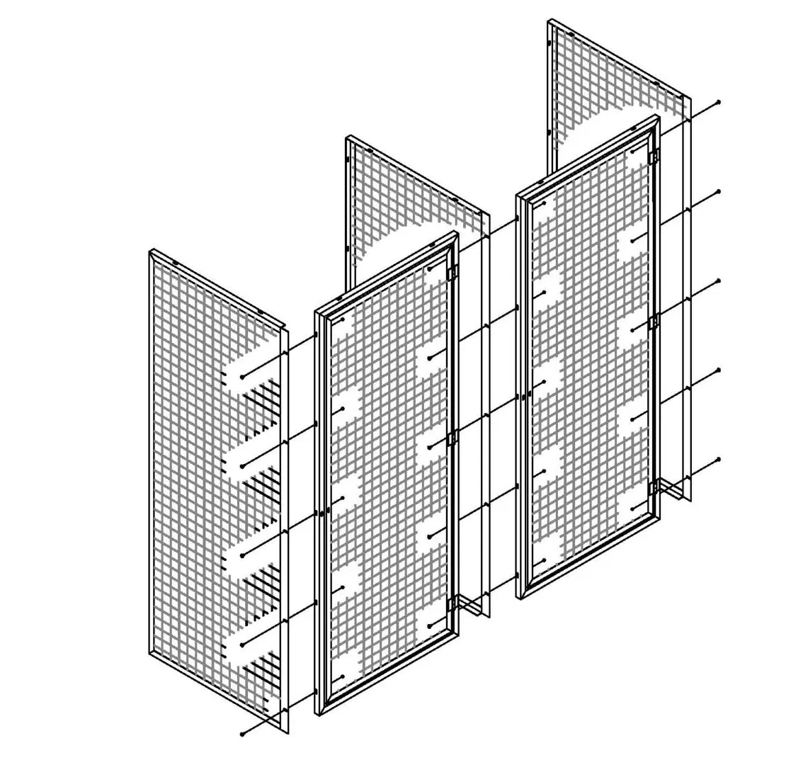
See the angle sections, overlapping round wires, shared dividers, hinges, and connection hardware as a complete locker row. Rotate the view, switch tiers, open the doors, or separate the components.
PROGUARD / CONSTRUCTION IN 3D
- Starting Return
- Prehung Door Assembly
- Opposite Return
- Back Panel
- Ceiling
Illustrative 3′ × 3′ bays, 7′ 6″ high, shown with backs and ceilings. Display details remain subject to project review; this is not a fabrication drawing or installation sequence.
How ProGuard Tenant Lockers Fit The Room
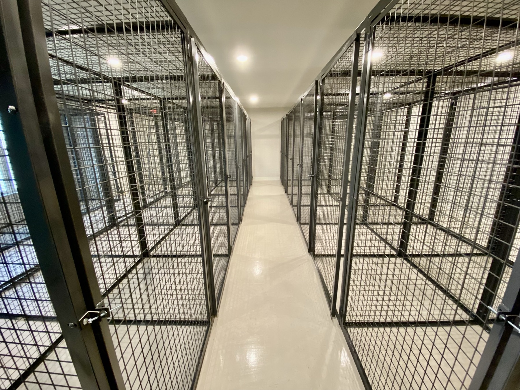
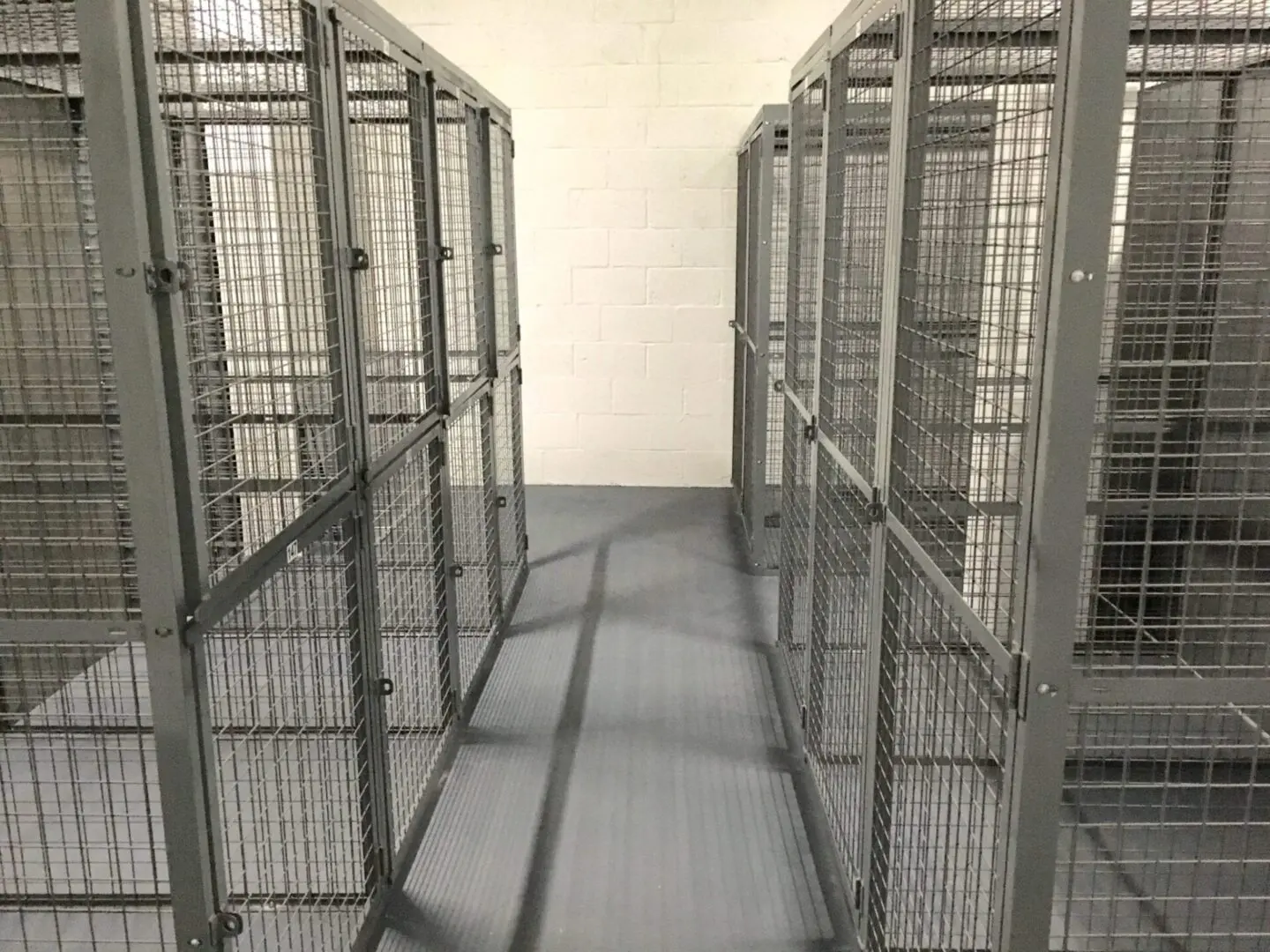
ProGuard tenant storage lockers give each resident a separate lockable compartment within a shared room. Steel angle frames hold the wire mesh, and adjoining lockers share dividers. Single-tier lockers provide one tall compartment; double-tier lockers divide that height into two independently accessed spaces.
The useful layout depends on more than locker count. Leave room for aisles and door swings, check pipes and columns, and decide whether existing walls can form the backs. Then choose sizes, locks, finish, ceilings, and shelves. Send your layout or room dimensions to us for a dimension and component review.
Specification Schedule
| Component | Size / Material | Construction Detail |
|---|---|---|
| Standard Mesh | 10-gauge steel wire; nominal 2″ × 2″ square welded mesh | Welded at intersections and attached to the frame; confirm clear opening when a precise pass-through dimension matters. |
| Steel Angle | 1¼″ × 1¼″ legs × ⅛″ thickness | L-shaped section; ⅛″ equals 0.125″. Used as described for each component below. |
| Flat Stock | 2″ width × ⅛″ thickness | Used at front-return leading edges and back-panel vertical sides. |
| Panel Connection Slots | 5/16″ width × 1″ length; 20″ on center | Assembly slots in applicable panel framing, not the wire-mesh opening or a universal door-leaf hole pattern. |
| Front Return | Angle on top, bottom, rear; flat stock at front vertical edge | Forms sides and shared dividers at the aisle-facing portion of the run. |
| Back Return | 1¼″ × 1¼″ × ⅛″ angle on all four sides | Extends deeper enclosures; joins the front return angle-to-angle. |
| Back Panel | Top/bottom angles; 2″ × ⅛″ vertical flats | Rear closure; standard welded mesh or optional 16-gauge sheet steel. |
| Fixed Front / Ceiling Panels | 1¼″ × 1¼″ × ⅛″ angle on all four sides | Optional framed closures with 5/16″ × 1″ connection slots at 20″ on center. |
| Door Leaf & Outer Frame | 1¼″ × 1¼″ × ⅛″ angle; factory-prehung assembly | Moving leaf within a fixed four-sided buck; confirm handing and clear opening. |
| Hinges & Door Stops | Three 2½″ × 3″ spun-pin hinges; two 2″ × 1½″ stops per door | Padlock-hasp preparation standard; keyed-lock options available. |
| Hasp Clip | 1¼″ × 1¼″ × ⅛″ angle clip; 5/16″ × ¾″ slot | Separate round hole accepts the padlock; lock selection and final preparation follow the project. |
| Connection Hardware | ¼-20 carriage bolts with KEP nuts | ¾″ and 1″ lengths appear in the installation guide; use the length shown for the specific joint. Anchors depend on the substrate. |
| Nominal Locker Sizes | 7′ 6″ high; 3′, 4′, 5′, or 6′ wide; 3′, 4′, or 5′ deep | Overall nominal dimensions are not the clear door opening or usable interior dimensions. Custom layouts reviewed. |
| Tier Arrangement | Single full-height or two stacked compartments | Double-tier bays provide two separately accessed compartments; confirm shelf and compartment dimensions. |
| Standard Finish | Electrostatically applied enamel: Battleship Gray or Jet Black | Powder coating and galvanizing options are reviewed for the project environment. |
These are nominal product details, not fabrication cut sizes. Your quote and approved drawings identify the actual dimensions, infill, finish, closures, accessories, and hardware.
Product details
Specifications At A Glance
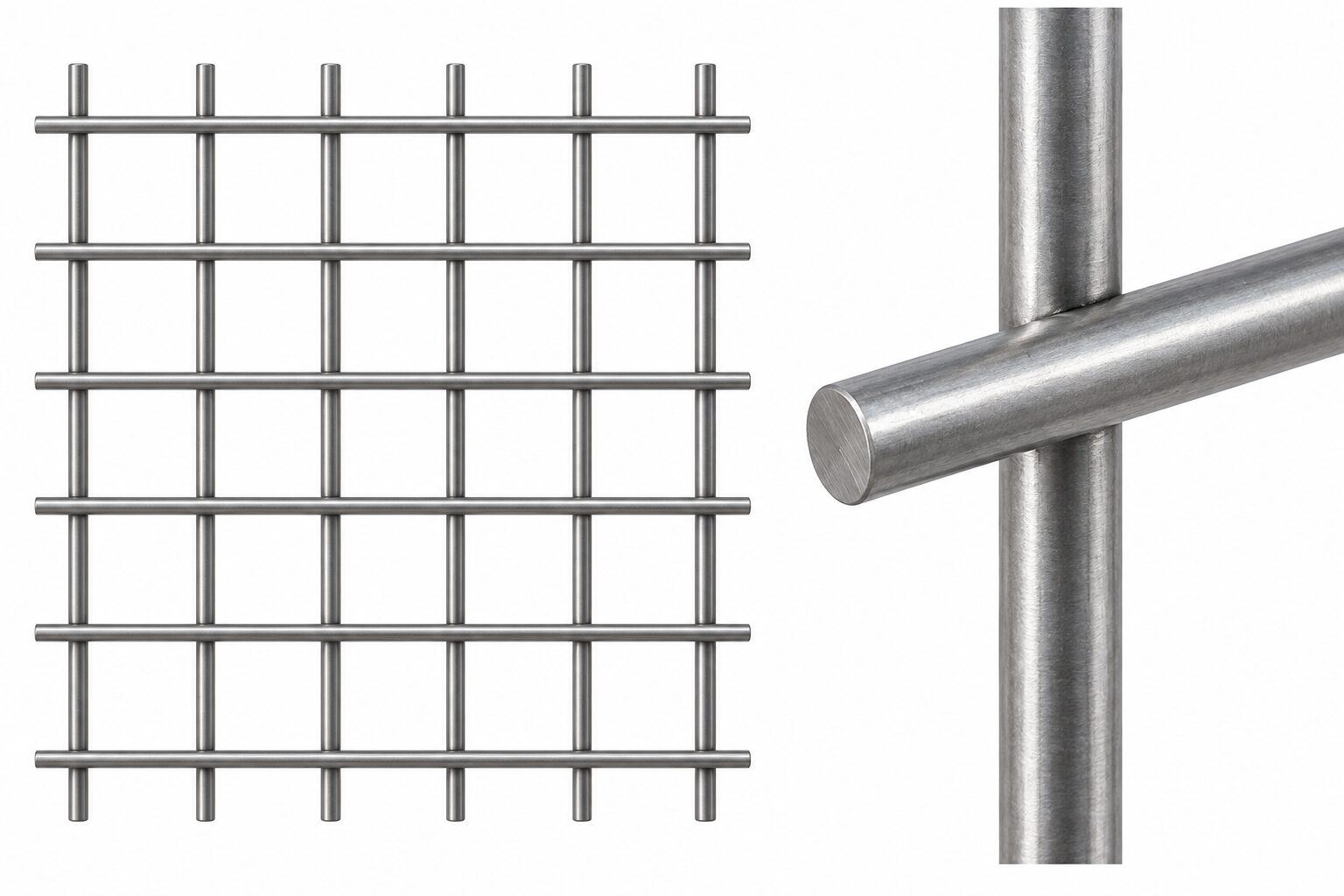
Welded Wire Mesh Close-Up
Inside Frame Connection
A closer look at the construction
Mesh Welded To The Angle Frame
The view from inside the locker shows how the welded wire mesh attaches to the steel-angle panel frame.
- 1Mesh-to-frame welds. The mesh overlaps the flat leg of the angle and is welded to the frame.
- 2Overlapping wire layers. Straight wires sit on top of one another and are welded at their crossings. Standard mesh is 10 ga., 2 in. × 2 in.
- 3Inside-facing angle leg. The open side of the 1¼ in. × 1¼ in. × ⅛ in. angle frame faces the locker interior.
Welds are highlighted for visibility; weld size and spacing are not specified by this illustration.
Compare mesh & infill options →Construction, starter & add-on details
How your locker system comes together
Plan The Mesh, Framing, Layout, Accessories, Finish, And Locks
Start with the standard construction, then choose the arrangement and only the options your room needs. Open any step for the detailed section below.
- 01
 Start with the standard2 in. × 2 in. welded wire mesh10-gauge steel provides the open, visible enclosure surface. Other infills are available for selected projects.
 - 02Support the mesh1¼ in. steel-angle framingThe standard mesh is secured in a 1¼ in. × 1¼ in. × ⅛ in. angle-iron frame to create rigid modular panels.
- 03Choose resident capacitySingle tier or double tierSingle tier gives one resident a full-height compartment. Double tier stacks two compartments to create more openings in the same floor area.
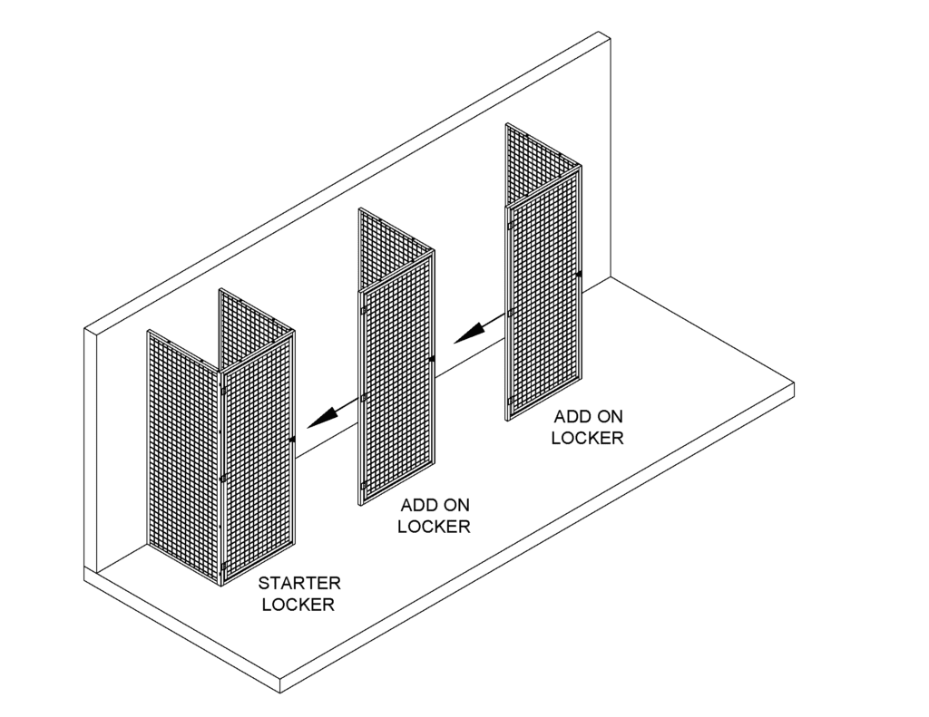
- 04Build an efficient rowStarter and add-on unitsThe starter begins a row. Add-on lockers extend it and share adjoining divider conditions, so the layout—not just the opening count—determines the parts.
- 05Close and organize the compartmentBacks, ceilings, and shelvesAdd a back when an existing wall cannot close the rear, a ceiling when top security is needed, and shelves when residents need separated storage levels.
- 06Finish the systemColor, finish, door, and lockChoose the project finish and how residents will secure their doors—from the standard padlock hasp to available keyed-lock configurations.
Not sure which choices apply?Send a room sketch, approximate dimensions, the number of residents, and a few photographs. Newark Wire Works can help turn that information into a workable layout.Tell us about the room →
Shared panels in a locker row
Starter First Add-On Units Extend The Run
Adjoining lockers share dividers. The room layout determines the number of starter units, add-ons, end panels, and wall connections.
Starter Unit
Establishes the first complete opening in the run, including the beginning/end condition shown on the layout. It gives the installer the fixed starting point for alignment.
Add-On Unit
Extends the run beside the starter. Adjoining lockers share the scheduled partition or connection frame, which avoids duplicating a full side at every opening.
Final End Condition
The last opening still needs the correct return, divider, or wall closure. Corners, offsets, doors, and changes in depth can restart the logic.
Why A Layout Matters
The same opening count can require a different bill of material when the lockers form multiple rows, change depth, back up to one another, or stop at different walls.
Choose Your Material
Wire Mesh Options & Sheet-Metal Lockers
Compare the look and practical benefits of each infill. Start with standard welded wire, or ask NWW about a woven-wire, expanded-metal, or solid sheet-steel locker configuration.
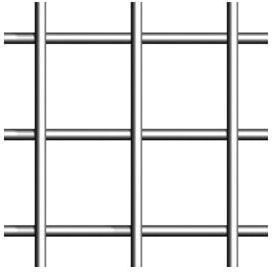
Standard Welded Wire
10-gauge wire · 2″ × 2″ square mesh
Straight wires are welded together at their intersections to form the standard ProGuard locker infill.
Benefits: Open visibility makes stored items easy to see, while the square openings allow air to move through the panels.
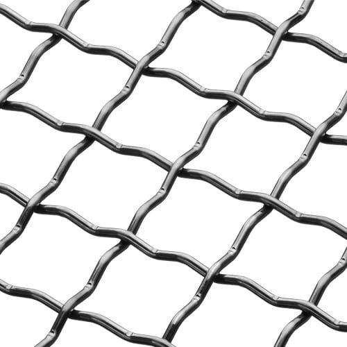
Diamond Woven Wire
10-gauge · 1½″ diamond · intercrimp woven
Woven wires form a familiar diamond pattern for an alternative to the square welded-wire appearance.
Benefits: An open design provides ventilation and visibility with a traditional wire-partition look.

Rectangular Woven Wire
10-gauge · 2″ × 1″ rectangle · intercrimp woven
Interlaced wire creates rectangular openings with a different visual rhythm from square or diamond mesh.
Benefits: Offers another architectural appearance while retaining an open, ventilated enclosure.

Heavy Woven Wire
6-gauge · 2″ diamond · intercrimp woven
A heavier wire option for projects that specify a more substantial woven infill.
Benefits: Thicker wire provides a heavier material section while keeping the benefits of an open mesh panel.
Flattened Expanded Metal
Flattened expanded steel · multiple gauges and opening sizes
Steel sheet is slit and stretched into a connected diamond pattern, then flattened.
Benefits: Provides a continuous metal network with openings for ventilation and a different screening appearance from wire mesh.
Sheet-Metal Lockers
16-gauge solid sheet-steel option
Solid steel infill creates locker panels that conceal stored belongings from view.
Benefits: A useful choice when privacy and a solid enclosure are priorities. Solid panels do not provide through-panel airflow; ventilation and the complete locker arrangement are coordinated for the project.
Mesh openings, wire size, finish, and framing are confirmed with your quote. Visibility and screening vary by the selected pattern. Material samples illustrate the infill, not a complete locker assembly.
Discuss Mesh & Sheet-Metal Locker Options →
Additional Mesh Data Sheets
Other wire patterns available for project review. These are separate from the standard locker infill shown above.
Framing & Panel Connections
Standard frame members are 1¼″ × 1¼″ × ⅛″ steel angle: two 1¼″ legs forming an L-shaped section, each ⅛″ (0.125″) thick. Connection flats are 2″ wide × ⅛″ thick. The arrangement of angle and flat stock changes by component, as described below.
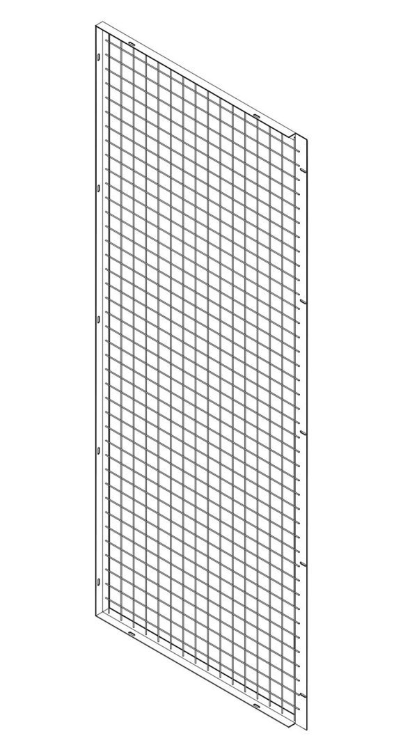
Front Return
The aisle-facing vertical edge uses 2″ × ⅛″ flat stock. The top, bottom, and rear edges use 1¼″ × 1¼″ × ⅛″ angle. Standard connection slots are 5/16″ wide × 1″ long at 20″ on center. Front returns form end panels and shared dividers at the front of a locker run.
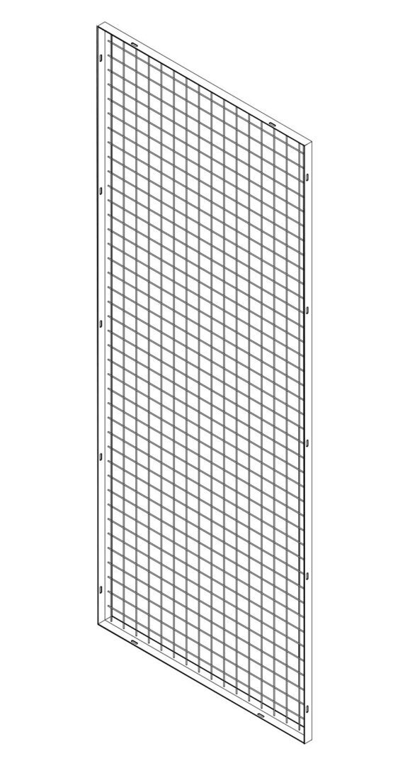
Back Return
A back return extends a deeper enclosure with 1¼″ × 1¼″ × ⅛″ angle on all four edges, with 5/16″ × 1″ slots at 20″ on center. It joins the front return angle-to-angle; its framing differs from a rear back panel.
Back Panels Are Different From Back Returns
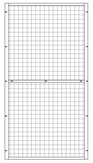
Back panels close the rear of the locker with 1¼″ × 1¼″ × ⅛″ top and bottom angles and 2″ × ⅛″ vertical flats. Framing has 5/16″ × 1″ slots at 20″ on center. Adjacent vertical flats overlap at the connection. Standard infill is 10-gauge 2″ × 2″ welded mesh; 16-gauge sheet-metal backs are also available.
Slotted Connections & Hardware
Panel-frame connection slots measure 5/16″ wide × 1″ long, spaced 20″ on center along the applicable members. These are assembly slots, separate from the openings in the mesh. Connections use ¼-20 carriage bolts and KEP nuts; the installation guide identifies ¾″ and 1″ bolt lengths for different joints.
Panel slots and door hardware preparation serve different purposes. Return-panel mounting slots are not a blanket instruction to punch the door leaves. Fastener length and joint grip follow the actual combination of members.
Finishes & Colors
Choose your paint color or compare the coating options for your project.
Painted Enamel
Electrostatically applied, air-dried enamel. Battleship Gray and Jet Black are our standard painted colors; include your preferred color with your quote request.
Need a specific paint color? Send the color reference or project specification with your plans.
Additional Finish Options
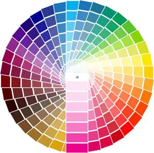
Powder Coating
Polyester powder coating in a project-selected color. Send the color code or approved sample and any specified coating requirements.
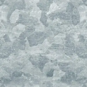
Hot-Dip Galvanizing
A zinc coating for compatible carbon-steel construction. Review this option for outdoor, damp, or other exposure conditions called out in the project specification.
Galvanizing + Powder Coating
Hot-dip galvanized steel with a powder-coated color finish. Specify both coatings so we can review the preparation, color, and complete finish system.
Color samples are illustrative. Confirm the final color and finish with an approved sample. Coating suitability depends on the selected material and construction; ask us about stainless steel, aluminum, or mill-galvanized and unpainted mesh.
How many residents should the row serve?
Single Tier Gives More Height Double Tier Creates More Compartments
Tap a door or use the buttons to open and close it. Double-tier doors operate independently.
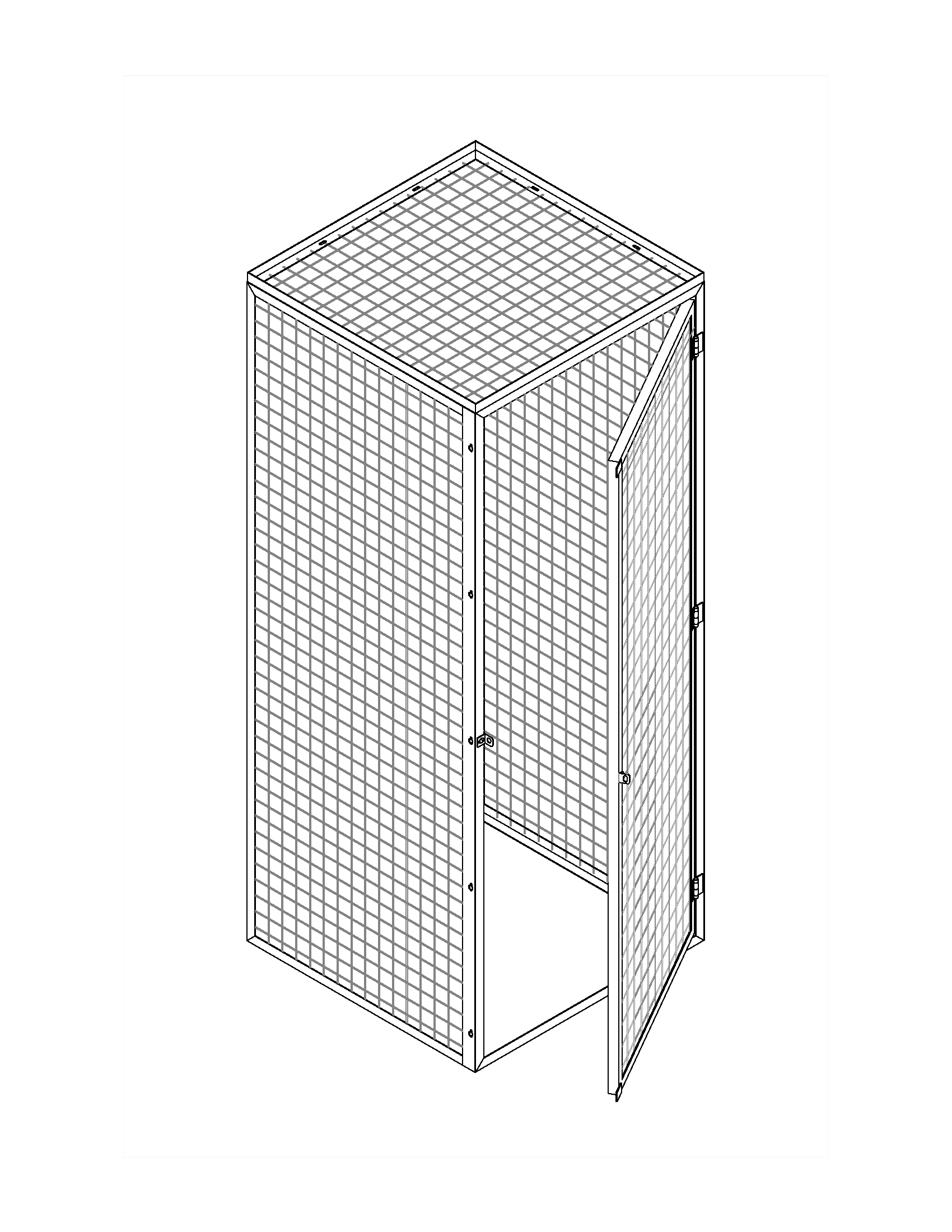
Door closed
Single tier
One Full-Height Compartment
One door serves one tall compartment. This is the better starting point for residents storing taller items or when uninterrupted vertical space matters more than the number of openings.
View original drawing ↗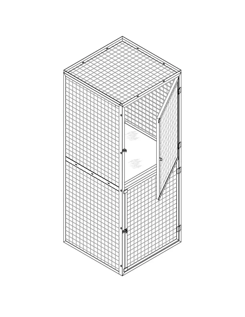
Upper door closed · Lower door closed
Double tier
Two Stacked Compartments
Two separate doors create an upper and lower compartment. This serves more residents along the same wall, but each resident receives less vertical storage space.
View original drawing ↗Custom / multi-tier
Custom Widths, Depths, Heights, And Tiers
Nonstandard heights, mixed sizes, multiple tiers, or special door access can be quoted from an exact room elevation and the desired clear openings.
Ask about a custom layout →Illustrative door movement. Final sizes, handing, and accessories follow the project layout.
Layout & Component Drawings
See each component up close. Select a drawing to open the larger original from the NWW tenant locker drawing library.
Back Panels
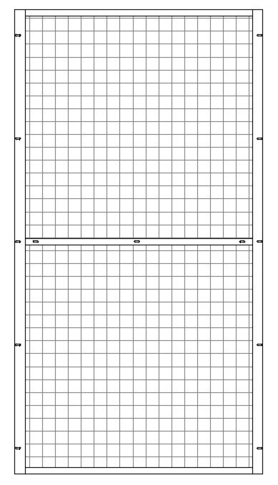
Rear closures use 10-gauge 2″ × 2″ welded mesh, 1¼″ × 1¼″ × ⅛″ top and bottom angles, and 2″ × ⅛″ vertical flats. A 16-gauge sheet-metal back is an available alternative.
Ceiling Panels
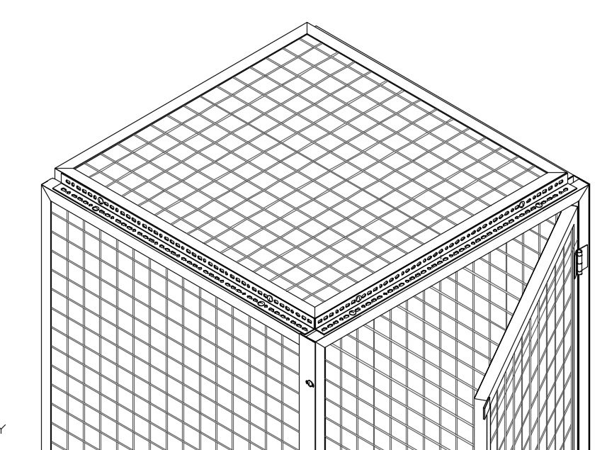
Optional ceilings use 10-gauge 2″ × 2″ welded mesh framed with 1¼″ × 1¼″ × ⅛″ angles on all four sides. Standard connection slots are 5/16″ × 1″ at 20″ on center. Coordinate ceiling supports and overhead clearances with the layout.
Mid-Shelf / Tier Divider
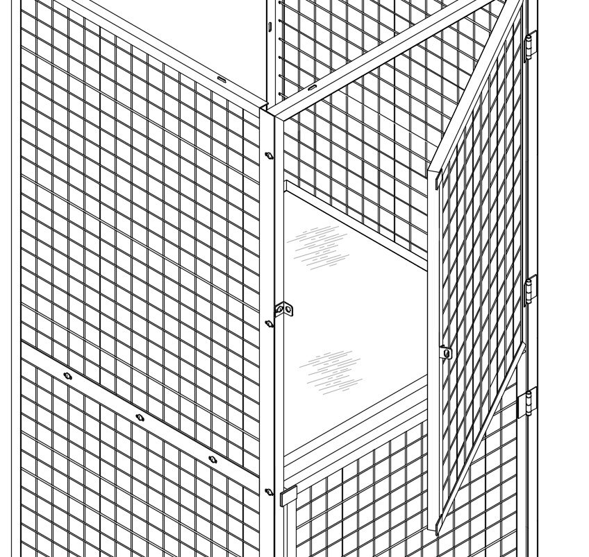
The horizontal divider separates the upper and lower compartments of a double-tier locker. Review shelf material and support requirements with the layout.
Fixed Front Panels
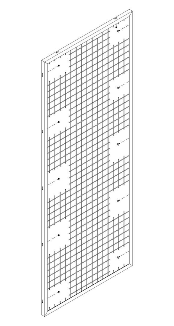
Fixed front panels fill the frontage beside a door. They use 1¼″ × 1¼″ × ⅛″ angles on all four sides, standard 10-gauge 2″ × 2″ welded infill, and 5/16″ × 1″ connection slots at 20″ on center.
Stiffener Top Channel
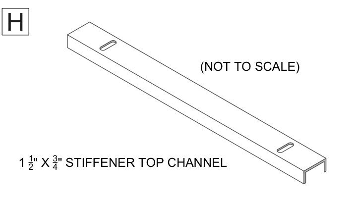
The manual’s Detail H shows the slotted top channel used to stiffen the assembly. Coordinate channel locations with the approved layout.
Padlock Hasp
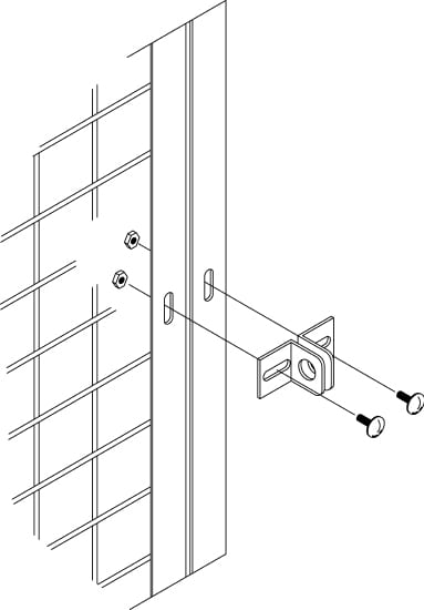
A padlock hasp secures the door to the buck. Confirm the locking arrangement and door handing before fabrication.
Optional Marks Lockset
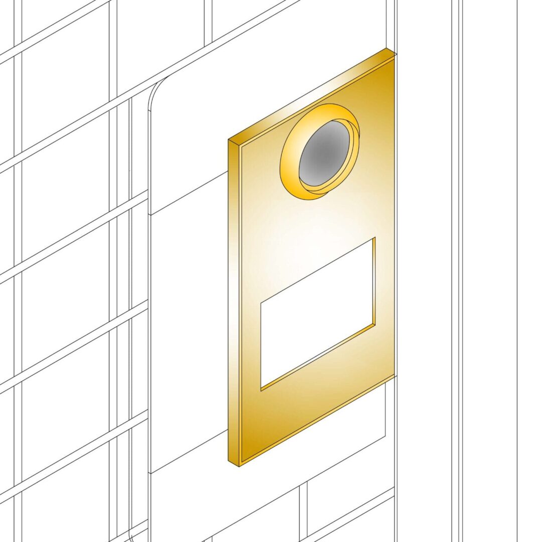
An alternative lock preparation for projects that require a lockset. Specify the access and keying requirements with your quote request.
Starter And Add-On Layouts
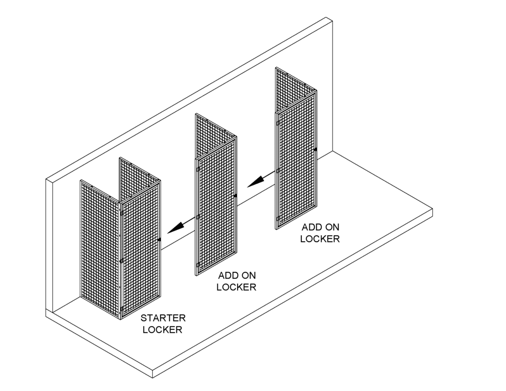
A starter establishes the first complete locker opening. Add-on bays share adjoining dividers. Ends, existing walls, corners, and changes in depth determine the remaining returns and closures. Count resident compartments separately from bays: a double-tier bay has two compartments.
Additional component drawings
Backs, ceilings, shelves, and supporting parts
Add Only What The Room And Each Compartment Need
An existing wall may close the back of a locker, or the system can include its own back. Ceiling panels close the top, shelves organize the interior, and supporting parts complete larger or less typical layouts. Select any illustration below to open the larger drawing.
Door panel
Factory-Prehung Access
Angle-framed mesh door in a four-sided outer frame, with three spun-pin hinges, door stops, and the selected lock preparation.
Front return
Locker Side At The Aisle
Forms the locker side from the door line toward the back. A 2-inch vertical flat at the front edge connects to the door or front panel; the remaining frame uses 1¼-inch angle.
Back return
Rear Side Extension
Extends the locker side when one return panel is not deep enough. It uses 1¼-inch angle on all four sides and joins the front return angle-to-angle.
Front panel
Fixed Infill Beside A Door
Completes an extra-wide locker face or an opening arrangement that cannot be made with the door frame alone.
Mesh is partly omitted in this detail to show the connections.Back panel
Independent Rear Closure
Closes the rear when an existing wall is unavailable or unsuitable. Standard mesh and selected sheet-metal configurations are available.
Ceiling panel
Top Security Closure
Angle-framed mesh closes the top. Allow clearance for structure, piping, lights, sprinklers, and installation access.
Shelf panel
Storage Within A Compartment
Provides an elevated storage surface supported at the scheduled height. Confirm material, size, elevation, and intended load during review.
Stiffener channel
Alignment Across Large Assemblies
Top channels and designated project hardware stabilize scheduled multi-panel or extra-large locker configurations.
Doors, Hinges & Access
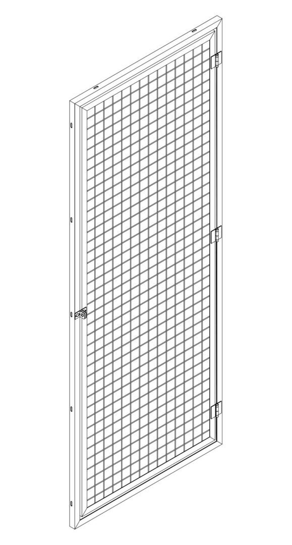
The Door Is Its Own Assembly
The moving door leaf and fixed four-sided outer frame (buck) both use 1¼″ × 1¼″ × ⅛″ steel angle. The door is factory prehung with three 2½″ × 3″ spun-pin hinges, two 2″ × 1½″ stops per door, and padlock-hasp preparation. Standard infill is 10-gauge 2″ × 2″ welded mesh.
In a double-tier unit, upper and lower leaves operate separately. Each compartment has its own door and access point. The model separates the opening angles so both leaves remain visible.
Show The Handing On The Plan
Locate the hinges and latch relative to the aisle, room entrance, and adjacent doors. A door needs room to swing without blocking the route residents use to carry belongings.
The 3D demonstration uses a representative right-hinged arrangement. It is a visual explanation; final handing, clear opening, lock selection, and hardware positions belong on the approved drawings.
Product details
Doors & Locks
Door security
Choose How Tenants And Management Will Operate The Door
The standard padlock hasp is simple and economical. A Marks 3700 Series mortise lockset is available when the project needs keyed operation, interchangeable-core planning, controlled keying, or alternate interior hardware.
An ADA-related low-threshold entrance and lever option can be reviewed for the locker door. The architect and project team must confirm the complete accessible route, maneuvering clearance, hardware, opening force, and applicable code requirements.
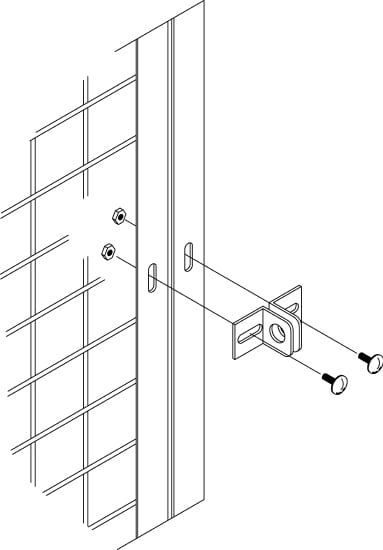
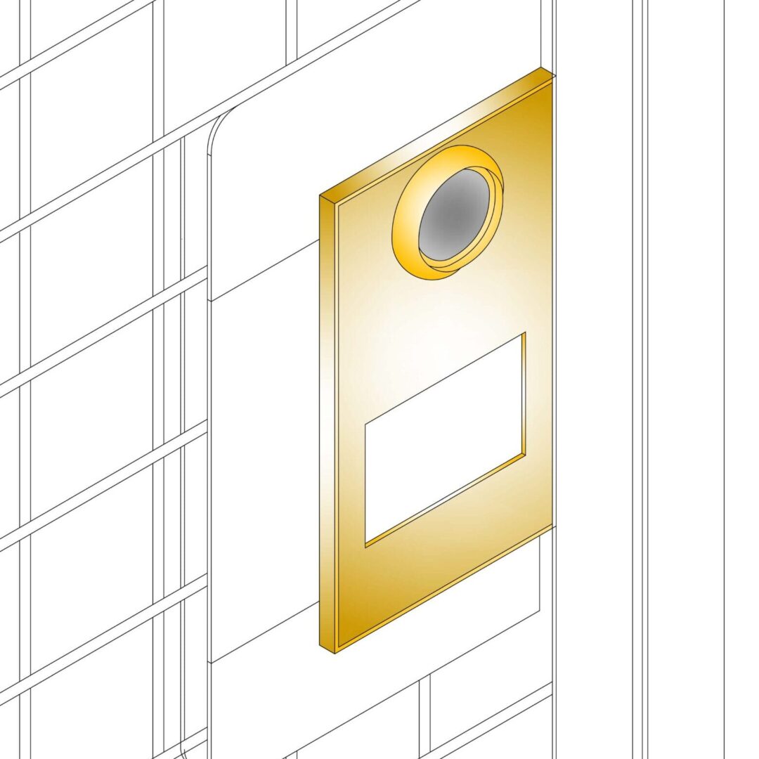
From the installation guide
Review The Locker Assembly Sequence
The drawings below are representative NWW details. The approved project drawing controls panel order, dimensions, connections, anchors, and designated hardware.
Field safety and coordination
Before drilling, verify the wall and floor substrates and locate concealed utilities, reinforcing, and post-tensioning. Coordinate accessibility, egress, sprinklers, lighting, ventilation, and required clearances with the project team and authority having jurisdiction. Security ceilings and shelves are not walking surfaces.
Documents for the office and field
Download, Mark Up, And Send Us The Room
Product brochureConstruction, sizes, mesh, finishes, and lock choicesDownload complete PDF ↓Planning sketch sheetDraw the room, locker rows, openings, and obstructionsDownload complete PDF ↓Resource centerSpecifications, installation documents, and product literatureSearch resources →
What to include with your quote request
Mark These Details On Your Room Plan
- 1Room width, depth, and clear ceiling height
- 2Quantity, tier, nominal locker width and depth
- 3Walls, doors, columns, piping, panels, and equipment
- 4Backs, ceilings, shelves, floor panels, locks, and finish
- 5Project address, required date, and installation scope
Built for apartments and condominiums
Turn One Shared Room Into Organized, Private Storage
Each resident gets a separate lockable compartment. The open wire design lets building management see through the enclosure and helps the room retain light and airflow.
The modular system can follow walls, turn corners, work around columns and piping, and make practical use of rooms that are not perfectly square. Newark Wire Works helps determine what the room needs—you do not have to design every panel yourself.
Frequently asked questions
Common Locker Layout And Installation Questions
What is the difference between a starter and an add-on unit?
The starter establishes the first complete locker condition in a run. Add-ons extend that run and share the adjoining divider or connection condition shown on the approved layout. A new row, corner, offset, or change in depth can change the required component count.
Do lockers need back panels?
Not always. An approved existing wall may form the rear boundary. Add back panels when there is no suitable wall, when the locker is freestanding, or when the required security boundary cannot rely on the existing construction.
How much clearance is needed above a ceiling panel?
Allow workable space for installation and coordinate structure, lights, sprinklers, piping, and ventilation. A 3-to-5-inch space may be a useful planning starting point in some rooms, but the approved design and authority having jurisdiction control the final arrangement.
Are shelves and floor panels available?
Yes. Shelves, ceiling panels, back panels, and floor panels can be included where scheduled. Send the desired shelf elevation, material, size, and intended use so the correct support and construction can be reviewed.
Can Newark Wire Works make custom sizes?
Yes. Standard planning sizes are the fastest starting point, but layouts can include custom widths, depths, heights, tiers, front panels, and multi-panel returns when the room requires them.
Can the locker use a keyed lock instead of a padlock?
Yes. The padlock hasp is standard. Marks 3700 Series lockset options can support keyed, interchangeable-core, and alternate interior-hardware requirements when selected and coordinated during quotation.
Does wire mesh automatically satisfy sprinkler or building-code requirements?
No single product statement can establish compliance for every building. Mesh visibility and airflow can help coordination, but the architect, fire-protection designer, code official, and authority having jurisdiction must approve the full room design.
Can Newark Wire Works install the lockers?
Installation availability can be reviewed with the quotation. Provide the project location, schedule, access restrictions, substrate information, working hours, and any prevailing-wage or site-specific requirements.
Ready to improve the storage room?
Send The Room Plan We Will Review The Layout And Required Components
PDFs, sketches, marked-up plans, CAD files, and photographs are all useful. Include what you know; NWW will help identify the missing decisions.
Before you request a quote